|
View: 8515|Reply: 29
|
All About Missiles and Anti Missiles.........
[Copy link]
|
|
|
First of all kalo thread ni dah ade bleh la Mod mergekan.........tapi puas den menyelak kat belakang td x jumpe pun........hehheeh
For this thread .......u can put anythings about missile and anti missiles syatem i.e SSM, SAM, ASM, AAM , Chaff, other Decoy, CIWS etc..........we also can discuss the Pro and cons of any missiles sytem u ever known.......
Aim for this thread is to developed non official source for online reference regarding Missiles and Anti Missiles.......(echeh poyo je ayat aku nih)
Cheers........ |
Rate
-
1
View Rating Log
-
|
|
|
|
|
|
|
|
|
|
|
|
Mak oiii thread ni boleh membesar giler nih...takpe teruskan! |
|
|
|
|
|
|
|
|
|
mat_toro This user has been deleted
|
|
Ni kalau merge dgn S300V vs patriot ok gak nih... |
|
|
|
|
|
|
|
|
|
|
|
Tomahawk Missile
Primary Function: Long-range subsonic cruise missile for attacking land targets.
Contractor: Hughes Missile Systems Co., Tucson, Ariz.
Power Plant: Williams International F107-WR-402 cruise turbo-fan engine; solid-fuel booster
Length: 18 feet 3 inches (5.56 meters); with booster: 20 feet 6 inches (6.25 meters)
Weight: 2,650 pounds (1192.5 kg); 3,200 pounds (1440 kg) with booster
Diameter: 20.4 inches (51.81 cm)
Wing Span: 8 feet 9 inches (2.67 meters)
Range: Land attack, conventional warhead: 600 nautical miles (690 statute miles, 1104 km)
Speed: Subsonic - about 550 mph (880 km/h)
Guidance System: Inertial and TERCOM
Warheads: Conventional: 1,000 pounds Bullpup, or
Conventional submunitions dispenser with combined effect bomblets, or
WDU-36 warhead w/ PBXN-107 explosive & FMU-148 fuze, or
200 kt. W-80 nuclear device
Date Deployed: 1983
Costs $500,000 - current production Unit Cost
$1,400,000 - average unit cost (TY$)
$11,210,000,000 - total program cost (TY$)
Total Program 4 170 missiles
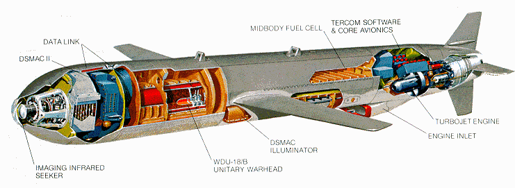
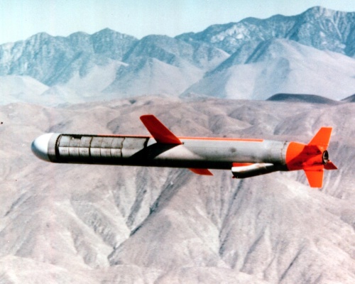
source from.....http://www.fas.org/man/dod-101/sys/smart/bgm-109.htm |
|
|
|
|
|
|
|
|
|
|
|
Introduction
The term missile in the post- World War II era has generally been used synonymously with "guided missile," due to the wide impact of guided missile technology upon the weapons field. In the un-guided case, initial conditions (such as train, elevation, powder charge in naval guns) and exterior ballistic effects are paramet-ers that, along with normal distribution, affect the "fall of shot." As advances in technology permitted (paralleled by in-creasing threat complexity), the development of guided missiles made possible a significant increase in terminal accuracy of mil-itary weaponry. The application of automatic control is preva-lent in broad regions of missile technology including:
Underwater Homing Torpedoes
Surface-to-Surface Aerodynamic Guided Missiles
Intercontinental Ballistic Missiles
Air-to-Air Guided Missiles
Surface-to-Air Guided Missiles
Guided Projectiles |
|
|
|
|
|
|
|
|
|
|
|
16.3 PHASES OF GUIDANCE
Missile guidance is generally divided into three phases--boost, midcourse, and terminal. These names refer to different parts of the flight path. The boost phase may also be called the launch-ing or initial phase.
16.3.1 Boost Phase.
Navy surface-to-air missiles accelerate to flight speed by means of the booster component. This booster period lasts from the time the missile leaves the launcher until the booster burns its fuel. In missiles with separate boosters, the booster drops away from the missile at burnout. The objective of this phase is to place the missile at a position in space from where it can either "see" the target or where it can receive external guidance signals. During the boost phase of some missiles, the guidance system and the aerodynamic surfaces are locked in position. Other missiles are guided during the boost phase.
16.3.2 Midcourse Phase.
The second, or midcourse, phase of guidance is often the longest in both distance and time. During this part of the flight, changes may be required to bring the missile onto the desired course and to make certain that it stays on that course. During this guidance phase, information can be supplied to the missile by any of several means. In most cases, the midcourse guidance system is used to place the missile near the target, where the
system to be used in the final phase of guidance can take over. In other cases, the midcourse guidance system is used for both the second and third guidance phases.
16.3.3 Terminal Phase.
The last phase of missile guidance must have high accuracy as well as fast response to guidance signals. Missile performance becomes a critical factor during this phase. The missile must be capable of executing the final maneuvers required for intercept within the constantly decreasing available flight time. The maneuverability of the missile will be a function of velocity as well as airframe design. Therefore, a terminal guidance system must be compatible with missile performance capabilities. The greater the target acceleration, the more critical the method of terminal guidance becomes. Suitable methods of guidance will be discussed in later sections of this chapter. In some missiles, especially short-range missiles, a single guidance system may be used for all three phases of guidance, whereas other missiles may have a different guidance system for each phase. |
|
|
|
|
|
|
|
|
|
|
|
16.4 TYPES OF GUIDANCE SYSTEMS
Missile guidance systems may be classified into two broad categories: missiles guided by man-made electromagnetic devices, and those guided by other means. (See figure 16-6.) In the
first category are those missiles controlled by radar, radio de- vices, and those missiles that use the target as a source of e-lectromagnetic radiation. In the latter category are missiles that rely on electromechanical devices or electromagnetic contact with natural sources, such as the stars (self-contained guidance systems).
All of the missiles that maintain electromagnetic radiation contact with man-make sources may be further subdivided into two subcategories.
(1) Control guidance missiles
(2) Homing guidance missiles
[ Last edited by bravotwozero at 10-8-2006 04:28 PM ] |
|
|
|
|
|
|
|
|
|
|
|
Control Guidance
Control guidance missiles are those that are guided on the basis of direct electromagnetic radiation contact with friendly control points. Homing guidance missiles are those that guided on the basis of direct electromagnetic radiation contact with the tar-get. Control guidance generally depends on the use of radar (radar control) or radio (radio control) links between a control point and the missile. By use of guidance information transmit-ted from the control point via a radio or radar link, the mis-sile's flight path can be guided. This chapter will use radar control guidance as a model for discussion because it is by far the most common application of control guidance methods. The principles discussed may be readily applied to radio (including television) control guidance.
16.4.1.1 Radar Control Guidance. Radar control guidance may be subdivided into two separate categories. The first category is simply referred to as the command guidance method. The second is the beam-rider method, which is actually a modification of the first, but with the radar being used in a different manner.
16.4.1.2 Command guidance--The term command is used to describe a guidance method in which all guidance instructions, or com-mands, come from sources outside the missile. The guidance sys- tem of the missile contains a receiver that is capable of re- ceiving instructions from ship or ground stations or from air- craft. The missile flight-path control system then converts these commands to guidance information, which is fed to the attitude control system.
In the command guidance method, one or two radars are used to track the missile and target. Figure 16-7 is a block diagram of how this method works in actual practice. As soon as the radar is locked on the target, tracking information is fed into the computer. The missile is then launched and is tracked by the radar. Target and missile ranges, elevations, and bearings are continuously fed to the computer.
This information is analyzed and a missile intercept flight path is computed. The appropriate guidance signals are then transmit-ted to the missile receiver. These signals may be sent by vary-ing the characteristics of the missile-tracking radar beam, or by way of a separate radio transmitter. The radar command guidance method can be used in ship, air, or ground missile delivery sys-tems. A relatively new type of command guidance by wire is now operational in some short-range antitank-type weapons. These systems use an optical sight for tracking the target while the weapons emits a characteristic infra-red signature, which is used for tracking the weapon with an IR sensor. Deviation of the wea-pon from the line of sight (LOS) to the target is sensed, and guidance commands are generated that are fed to the weapon con- trol system in flight via a direct wire link. Each weapon con- tains wire spools that pay out as the warhead flies out the line of sight to the target. Current usage of these systems is in relatively lightweight, portable, short-range battlefield envir-onments against armored targets where their high accuracy and substantial warheads are most efficiently employed.
16.4.1.3 Beam-rider Method--The main difference between the beam-rider method and the radar command guidance method is that the characteristics of the missile-tracking radar beam are not varied in the beam-rider system. The missile has been designed so that it is able to formulate its own correction signals on the basis of its position with respect to the radar scan axis. The technique is best understood after reviewing the principles of conical-scan tracking in Chapter 5. The missile's flight path control unit is sensitive to any deviation from the scan axis of the guidance radar and is capable of computing the proper flight path correction. An advantage of this type of system is that is requires only one radar. This radar must, of course, have a conical-scan feature in order to provide both target-tracking capability and a missile flight-path correction reference axis. A second advantage is that since the missile formulates its own directional commands, several missiles may be launched to "ride" the beam simultaneously, without the need for a cumbersome and complicated multiple-missile command system.
The accuracy of this system decreases with range because the radar beam spreads out, and it is more difficult for the missile to remain in its center. If the target is moving very rapidly, the missile must follow a continuously changing path, which may cause it to undergo excessive transverse accelerations
[ Last edited by bravotwozero at 10-8-2006 04:24 PM ] |
|
|
|
|
|
|
|
|
|
|
|
Originally posted by mat_toro at 10-8-2006 16:13
Ni kalau merge dgn S300V vs patriot ok gak nih...
kasi mod lain buat la...wa letih la... |
|
|
|
|
|
|
|
|
|
|
|
Homing Guidance
Homing guidance systems control the flight path by employing a device in the weapon that reacts to some distinguishing feature of the target. Homing devices can be made sensitive to a variety of energy forms, including RF, infrared, reflected laser, sound, and visible light. In order to home on the target, the missile or torpedo must determine at least the azimuth and elevation of the target by one of the means of angle tracking mentioned pre-viously. Active homing missiles will also have the means of de-termining range of the target if necessary. Tracking is perform-ed by a movable seeker antenna or an array with stationary elec-tronically scanned arrays in development for missiles and opera-tional in some torpedoes. Determination of angular error by amp-litude comparison monopulse methods is preferred over the older COSRO systems because of the higher data rate and faster response time; however, phase comparison monopulse or interferometer meth-ods have advantages in some applications. Homing guidance meth-ods may be divided into three types: active, semiactive, and passive homing (figure 16-9). These methods may be employed in seekers using any of the energy forms mentioned above, although some methods may be excluded by the nature of the energy form; for example, one would not build a passive laser seeker or an active or semi-active infrared seeker.
16.4.2.1 Active Homing. In active homing, the weapon contains both the transmitter and receiver. Search and acquisition are conducted as with any tracking sensor. The target is tracked employing monostatic geometry in which the returning echo from the target travels the same path as the transmitted energy (figure 16-8). An onboard computer calculates a course to in-tercept the target and sends steering commands to the weapon's autopilot. The monostatic geometry allows the most efficient reflection of energy from the target, but the small size of the missile restricts the designer to high frequencies and low power output from the transmitter, resulting in short seeker acquis-ition range.
16.4.2.2 Semiactive Homing. In semiactive homing, the target is illuminated by a tracking radar at the launching site or other control point. The missile is equipped with a radar receiver (no transmitter) and by means of the reflected radar energy from the target, formulates its own correction signals as in the active method. However, semiactive homing uses bistatic reflection from the target, meaning that because the illuminator platform and weapon receiver are not co-located, the returning echo follows a different path than the energy incident to the target. Due to its shape and composition, the target may not reflect energy efficiently in the direction of the weapon. In extreme cases the weapon may lose the target entirely, resulting in a missed in-tercept. This disadvantage is compensated for by the ability to use greater power and more diverse frequency ranges in an illum- ination device in a ship, aircraft, or ground station.
16.4.2.3 Passive Homing. Passive homing depends only on the target as a source of tracking energy. This energy can be the noise radiated by a ship or submarine in the case of a passive homing torpedo, RF radiation from the target's own sensors in the case of an anti-radiation (ARM) weapon, heat sources such as ship, aircraft, or vehicle exhausts, contrast with the tempera-ture or visible light environment, or even the radiation all ob-jects emit in the microwave region. As in the other homing meth-ods, the missile generates its own correction signals on the basis of energy received from the target rather than from a con-trol point. The advantage of passive homing is that the counter detection problem is reduced, and a wide range of energy forms and frequencies are available. Its disadvantages are its sus-ceptibility to decoy or deception and its dependence on a certain amount of cooperation from the enemy.
16.4.2.4 Retransmission Homing or Track Via Missile (TVM). Re-transmission homing is a blending of the characteristics of both command and semiactive homing guidance. In command guidance, missile steering commands are computed at the launch point using target position and missile position data derived from launch point sensors. In retransmission homing, the missile contains a semiactive seeker that determines the azimuth and elevation angle from the missile to the target, which is then coded and transmit-ted to the launch point via data link (down link). The fire-con-trol system at the launch point can use its own target tracking data, that of the missile (or both), and missile position data to compute steering commands, which are then transmitted to the mis-sile via an uplink. This technique is used in some new AAW mis-sile systems, including the U.S. Army Patriot system. Specific retransmission or TVM systems may vary somewhat from this ideal; however, they all will in some way use target angle data from the missile to compute steering commands at the launch point that are then transmitted to the missile.
16.4.3 Accuracy. Homing is the most accurate of all guidance systems because it uses the target as its source when used a-gainst moving targets. There are several ways in which the hom-ing device may control the path of a missile against a moving target. Of these, the more generally used are pursuit paths and lead flight paths, which are discussed in a subsequent part of this chapter. Because monopulse methods in weapons seekers are advantageous and are becoming the method of choice in current weapons, it is necessary to address the two basic types:
16.4.3.1 Amplitude Comparison Monopulse. This method, described in Chapter 5, requires a gimballed seeker antenna covered by a radome at the nose of the weapon. Because of aerodynamic re-quirements, the radome shape is normally not optimal for radar performance. Very precise orders to the antenna are required to achieve target acquisition due to the single antenna's limited field of view. In these systems the size of the antenna directly determines the limits of the frequency range of the seeker. Its primary advantage is its consistent performance throughout the potential speed and maneuverability range of potential targets.
16.4.3.2 Interferometer (Phase Comparison Monopulse). The in-terferometer eliminates the requirement for a movable antenna, having instead fixed antennas mounted at the edge of the airframe or on the wing tips, the result being reduced complexity and a wider field of view. As depicted in figure 16-10, two antennas separated by a known distance are installed for each mobility axis of the weapon. In the diagram the antennas A and B, separated by the distance d, receive energy emitted (passive homing) or reflected (semiactive homing) from the target.
Because the distance to the target is relatively large, it is assumed that the RF energy arrives as a series of planar waves with wavelength . In accordance with the discussion of electronic scanning in Chapter 7 and towed acoustic arrays in chapter 9 it is evident that for the geometry pictured, the phase sensed by antenna B will lag that sensed by antenna A by some phase angle which is proportional to d sin ; therefore:
= 2d sin
If is known and the phase angle can be determined, then the look angle, , can be calculated.
The interferometer provides the advantage of wide field of view, flexibility in airframe design, unobstructed use of weapon interior space, and the ability to cover broad frequency bands without constraints imposed by limited antenna size. The separation between the antennas governs the performance of the system, with missile body diameter or fin spread separation as the usual arrangement. The disadvantage of the interferometer is the angular ambiguity that may exist for wavelengths less than the separation between the antennas at a specific angle of incidence. If the distance between the antennas at an angle of incidence is d sin , and is less than d sin , then it is not possible to determine if the phase angle measured is just that or + n2 radians, where n is any integer. However, this is a minor problem in most homing systems because the absolute look angle is not as important as the rate of change of that angle.
The interferometer has an advantage in resolving multiple targets at twice the range of a typical amplitude comparison monopulse seeker in the same size weapon. This gives the missile twice the time to respond to the changeover from tracking the centroid of the group to tracking one specific target, thus in-creasing the hit probability.
16.4.4 Composite Systems. No one system is best suited for all phases of guidance. It is logical then to combine a system that has good midcourse guidance characteristics with a system that has excellent terminal guidance characteristics, in order to in-crease the number of hits. Combined systems are known as compos-ite guidance systems or combination systems.
Many missiles rely on combinations of various types of gui-dance. For example, one type of missile may use command guidance until it is within a certain range of a target. At this time the command guidance may become a back-up mode and a type of homing guidance commenced. The homing guidance would then be used until impact with the target or detonation of a proximity-fixed war-head.
reference taken from........http://www.fas.org/man/dod-101/navy/docs/fun/part15.htm
[ Last edited by bravotwozero at 10-8-2006 04:32 PM ] |
|
|
|
|
|
|
|
|
|
mat_toro This user has been deleted
|
Originally posted by alphawolf at 10-8-2006 04:25 PM
kasi mod lain buat la...wa letih la...
susah ker nak merge?? Gua pun tak tau beb... |
|
|
|
|
|
|
|
|
|
|
|
|
x pe xyah merge carry on je kat c ni pun bleh......... |
|
|
|
|
|
|
|
|
|
|
|
Harpoon....
The AGM-84D Harpoon is an all-weather, over-the-horizon, anti-ship missile system produced by Boeing [formerly McDonnell Douglas]. The Harpoon's active radar guidance, warhead design, and low-level, sea-skimming cruise trajectory assure high survivability and effectiveness. The missile is capable of being launched from surface ships, submarines, or (without the booster) from aircraft. The AGM-84D was first introduced in 1977, and in 1979 an air-launched version was deployed on the Navy's P-3 Orion aircraft. Originally developed for the Navy to serve as its basic anti-ship missile for fleetwide use, the AGM-84D also has been adapted for use on the Air Force's B-52G bombers, which can carry from eight to 12 of the missiles.
The AGM-84D Harpoon Block 1D (with a larger fuel tank and reattack capability) was developed in 1991. With the reduced threat because of the break-up of the Soviet Union, this upgrade was shelved and never produced.
The AGM-84E Harpoon/SLAM [Stand-Off Land Attack Missile] Block 1E is an intermediate range weapon system designed to provide day, night and adverse weather precision strike capability against high value land targets and ships in port. In the late 1980s, a land-attack missile was needed. Rather than design one from scratch, the US Navy took everything from Harpoon except the guidance and seeker sections, added a Global Positioning System receiver, a Walleye optical guidance system, and a Maverick data-link to create the Stand-off Land Attack Missile (SLAM). The AGM-84E uses an inertial navigation system with GPS, infrared terminal guidance, and is fitted with a Tomahawk warhead for better penetration. SLAM can be launched from land-based or aircraft carrier-based F/A-18 Hornet aircraft. It was employed successfully in Operation Desert Storm and UN relief operations in Bosnia prior to Operation Joint Endeavor.
The SLAM-ER (Expanded Response) Block 1F, a major upgrade to the SLAM missile that is currently in production, provides over twice the missile range, target penetration capability, and control range of SLAM. SLAM-ER has a greater range (150+ miles), a titanium warhead for increased penetration, and software improvements which allow the pilot to retarget the impact point of the missile during the terminal phase of attack (about the last five miles). In addition, many expansions are being made to improve performance, survivability, mission planning, and pilot (man-in-the-loop) interface. The SLAM-ER development contract was awarded to McDonnell Douglas Aerospace (Now BOEING) in February of 1995. SLAM-ER achieved its first flight in March of 1997. All Navy SLAM missiles are currently planned to be retrofitted to SLAM-ER configuration. About 500 SLAM missiles will be converted to the SLAM-ER configuration between FY 1997 and FY 2001.
The SLAM-ATA (Automatic Target Acquisition) Block 1G, a follow on enhancement to SLAM-ER with reattack capability and new seeker, is under development. SLAM-ERs equipped with ATA will match the seeker images of a target scene with an on-board reference image. This process will improve the missile's ability to strike targets in cluttered spaces, such as urban areas. It will also improve missile targeting capability in poor weather, counter measure protected environments, and better enable offset aimpoint targeting.
The Harpoon Block II is an upgrade program to improve the baseline capabilities to attack targets in congested littoral environments. The upgrade is based on the current Harpoon. Harpoon Block II will provide accurate long-range guidance for coastal, littoral and blue water ship targets by incorporating the low cost integrated Global Positioning System/Inertial Navigation System (GPS/INS) from the Joint Direct Attack Munitions (JDAM) program currently under development by Boeing. GPS antennae and software from Boeing's Standoff Land Attack Missile (SLAM) and SLAM Expanded Response (SLAM ER) will be integrated into the guidance section. The improved littoral capabilities will enable Harpoon Block II to impact a designated GPS target point. The existing 500 pound blast warhead will deliver lethal firepower against targets which include coastal anti-surface missile sites and ships in port. For the anti-ship mission, the GPS/INS provides improved missile guidance to the target area. The accurate navigation solution allows target ship discrimination from a nearby land mass using shoreline data provided by the launch platform. These Block II improvements will maintain Harpoon's high hit probability while offering a 90% improvement in the separation distance between the hostile threat and local shorelines. Harpoon Block II will be capable of deployment from all platforms which currently have the Harpoon Missile system by using existing command and launch equipment. A growth path is envisioned for integration with the Vertical Launch System and modern integrated weapon control systems. With initiation of engineering and manufacturing development in 1998, initial operational capability for Block II will be available by 2001.
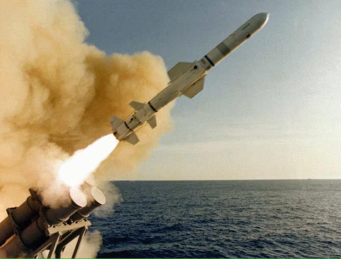
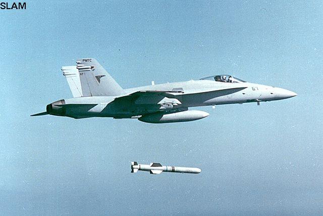
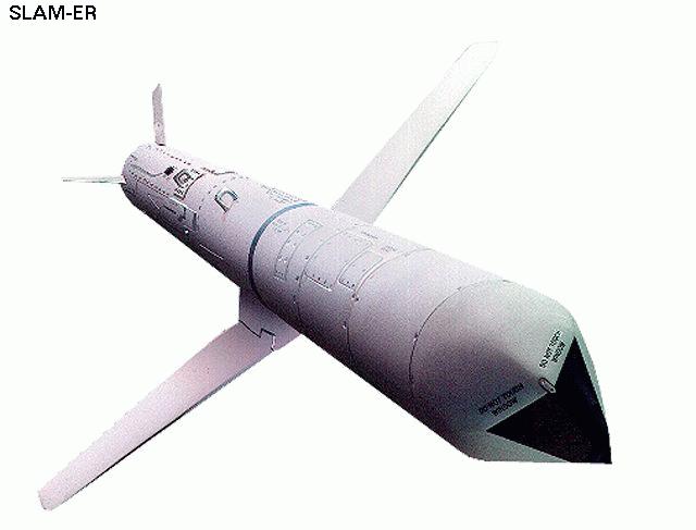
http://www.fas.org/man/dod-101/sys/smart/agm-84.htm
[ Last edited by bravotwozero at 10-8-2006 04:47 PM ] |
Rate
-
1
View Rating Log
-
|
|
|
|
|
|
|
|
|
|
|
Originally posted by mat_toro at 10-8-2006 16:35
susah ker nak merge?? Gua pun tak tau beb...
bukan la..sebab wa bz merge, split dengan delete...pendek kata ethnic cleansing kat TNSE |
|
|
|
|
|
|
|
|
|
|
|
Exocet Families....
The Exocet is built by MBDA, a European missile company. It is one of the most successful anti-ship missiles in service. Development began in 1967 as a ship-launched missile named MM 38. The air-launched Exocet was developed in 1974 and entered service with the French Navy five years later.
The missile is designed to hit large warships. It is guided inertially in mid-flight, and turns on active radar late in its flight to find and hit its target. Its solid propellant engine gives the Exocet a maximum range of 70 km. The submarine-launched version places the missile and a Naval booster motor within a launch capsule.
The Exocet has been manufactured in a number of versions, including:
MM38 (surface-launched)
AM39 (air-launched)
SM39 (submarine-launched)
MM40 (surface-launched)
The newest MM40 version (MM40 block 3) has an improved range of 180 km, through the use of a turbojet engine.


USS Stark hit by 2 exocets...
source from...http://en.wikipedia.org/wiki/Exocet_missile |
Rate
-
1
View Rating Log
-
|
|
|
|
|
|
|
|
|
|
|
moral nya, kita memerlukan lebih byk mende mende tu seme ..
tapi aku suka kalo kita bykkan dari darat ke udara .. kalo tak byk pon, mercun pon ok gak laaaa .. he he he |
|
|
|
|
|
|
|
|
|
|
|
ok ke
|
Masa negara aman ni kita perlu perbanyakkan kajian utk membangunkan missile ni..kita sepatutnya berkongsi idea dgn indonesia, pakistan dan iran serta china... Sebab dgn cara berkongsi sahaja kita dpt jimat kos sbg contohnya spt negara2 Nato BUat... |
|
|
|
|
|
|
|
|
|
|
|
|
dlm mase aman ni jugak kte kene memperbanyakkan usaha inovatif atau paling cokia pun reverse engineering whatever military tech yang ade |
|
|
|
|
|
|
|
|
|
|
|
Grandaddy of SAMs - WW2 German (non-operational however) Wasserfall (Waterfall)

The Wasserfall (Waterfall) anti-aircraft rocket is one of the most advanced projects of its type to come out of German wartime development. Guided by ground based radars, the Wasserfall rocket would have been tracked by one installation while another would track the target. A computer would then correlate the data and determine when the warhead should be detonated. It was designed to utilize types of fuels which would allow the missile batteries to stand ready for firing for up to one month without reloading. The first launch took place on the 8th of January 1944 and was a failure. The following February 1944 saw a successful launch which reached a speed of 2,772 km/h in vertical flight. When the program was canceled on the 6th of February 1945 nearly 40 flights had been made. After the war, captured Wasserfall reports would form the basis of the highly successful U.S. built "Nike" family of SAMs |
|
|
|
|
|
|
|
|
|
|
|
sometimes aku wonder jugak apasal since we already use Skyguard and Aspide, kita tak integrate our existing skyguard with aspide as below
skyguard/aspide
Aspide/Albatros on our laksamana

credit Hijjazain (member kita kan) |
|
|
|
|
|
|
|
|
|
| |
|